ClockDrift App User Guide
ClockDrift is an Android app that serves to measure clock drift, resp. time drift, in multimedia playback and recording devices. Clock drift leads, among others, to problems of differing playback speeds when synchronizing multiple audio and/or video recordings from different recordings devices. This app helps to measure the drifts in devices, making it easier to remove them in post-production, and helping to find devices that go well together with minimal relative drift. It basically works by playing back a test tone on the device that wants to be measured, and analyzing the tone on the measurement device running the app. It was developed as part of a research project at the Institute of Information Technology at Alpen-Adria-Universität Klagenfurt.
Here’s a short video introducing the problem and demonstrating the usage of the app:
Contents
Usage Example
You want to videotape a one hour long talk of a colleague with two smartphones from two perspectives. A shot of the full scene with the first, and a close-up of the speaker with the second. You then want to load them into a multitrack video editor on your computer, synchronize them and produce a nice video by dynamically cutting between the two recorded angles. Since you have an LG Nexus 4 and a Samsung Galaxy SII phone, you want to find out if it is a good idea to use these two devices for recording, you measure them with ClockDrift, and you discover that there’s a relative drift of 16.4 milliseconds per minute between them, amounting to an offset of 1 second after an hour - which is definitely too much and totally destroys every synchronized experience. Since your colleague has just bought a new LG Nexus 5 phone, you ask him to provide it for a measurement. You discover that the drift between the Nexus 4 and Nexus 5 is much lower at just 0.2 ms/min, which amounts to only 12 milliseconds after an hour, low enough for a great recording and video production experience.
Use Cases
- Measuring the deviation of the sampling rate of a device from its nominal value
- Measuring relative drift between devices
- Determining how well devices fit together for parallel recording
- Determining speed correction factors for post-production
- Measuring absolute drift of devices when the app is calibrated
- Measuring the drift of a device’s real time clock if driven by the same crystal oscillator as the audio DAC
- Measuring drifts between computers on a network
- Determining buffer underruns/overruns in multimedia streaming
Measuring the Drift
A measurement involves two devices. The device to be measured, which can be an arbitrary multimedia device, and the measurement device, which is an Android device running ClockDrift. By default, the measured drift is the relative difference between the two devices, which suffices to determine with similar drift rates for parallel recording purposes. The app offers also a calibration option called drift compensation, which, when correctly set, turns the device into an absolute measurement instrument to measure the absolute drift from the true time (UTC).
Measuring an Android Device
Install and start the app on both devices. Make sure they are set to the same frequency (default is 440 Hz), select “Play Test Tone” on the device to be measured, and hit “Analyze” on the measurement device. The measurement device needs to hear the test tone, and for accurate measurements, it is advised to keep background noise to a minimum.
Starting with Android 4.0, ClockDrift supports Android Beam. You can beam the app to another Beam-enabled Android device, which starts an automatically configured measurement (or installs the app if missing). The device that initiates the beam is always going to be measured by the receiving device, which also automatically receives data about the device model being measured that shows up in the results.
Measuring a non-Android Device
First, set up a test tone. To measure an arbitrary device like an audio recorder, a computer soundcard, an MP3 player, a video camera, an iPhone or iPad, open the app and select “generate test tone” from the menu on the action bar (top right). This generates a test tone with a length of one minute by default. When the process is finished, you can find a wav-file in the root directory of your device storage, named testtone-*.wav. Copy this test tone to the device that you want to measure and play it back. Alternatively, if you want to measure another “smart”-OS like Windows Phone or iOS, you can look for a frequency generator app, set its output to the measurement frequency, and play the test tone from there. Keep in mind that the measurement device needs to hear the tone, hit “Analyze” in the main screen of the app and watch as it measures.
Screens
Main Screen
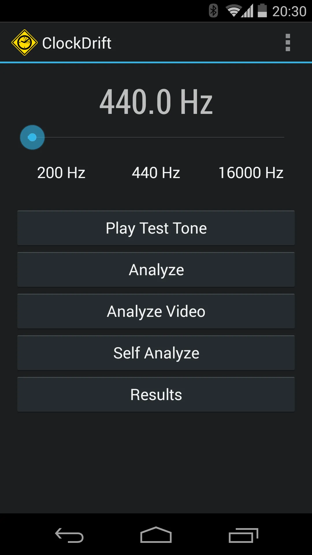
The main screen is the entry point to the apps functions. It offers the following options:
Frequency selector: This is the frequency that will be used for the drift analysis. There are presets to choose from, but you can also set a custom frequency with the slider or by tapping the frequency label and typing it in. You need to take care that for a measurement, both devices must be set to the same frequency (which is automatically set when using Android Beam), the playback device’s hardware must be able to emit the frequency, and the measurement device’s hardware must be able to pick it up. Technically it doesn’t have an important impact on the measurement quality.
- A440 (440 Hz): Default frequency, proven to work with all tested devices and the default setting. Can sound annoying over time though, especially for coworkers in your office ;)
- SMPTE (1 kHz): The signal you might know from the TV test pattern. Sounds even more annoying.
- Ultra (20 kHz): An imperceptible ultrasonic signal, which is the preferred method due to its unobtrusiveness. It is only available on devices whose hardware sampling rate is >= 48 kHz, else this button is grayed out.
Play test tone: Used on a device to be measured. It just plays back the test tone that the measuring device picks up and analyzes. This is a convenience function for Android devices, other platforms can use frequency generator apps of a generated test tone file.
Analyze: Starts a measurement and analyzes the incoming signal.
Analyze Video: Since Android doesn’t allow to directly access the audio data stream in a video recording process, this option provides the possibility to load and analyze a pre-recorded video from a camcorder app. Only available in Android 4.1 and up. Read more about video analysis below.
Self Analyze: The app measures its own device by playing back the test tone through the speaker and directly picking it up from the microphone and analyzing it. It can be used to check if the device supports the selected frequency, e.g. when getting a continuous “weak signal” warning on the analysis screen. Can also be used to check if the playback and recording pipelines use the same clock signal, which is typically the case since all of that functionality is usually in one and the same audio processing chip. The measured drift should be zero and is usually oscillating with a small variation around zero.
Results: Opens the list of saved measurement results.
Action Bar Menu
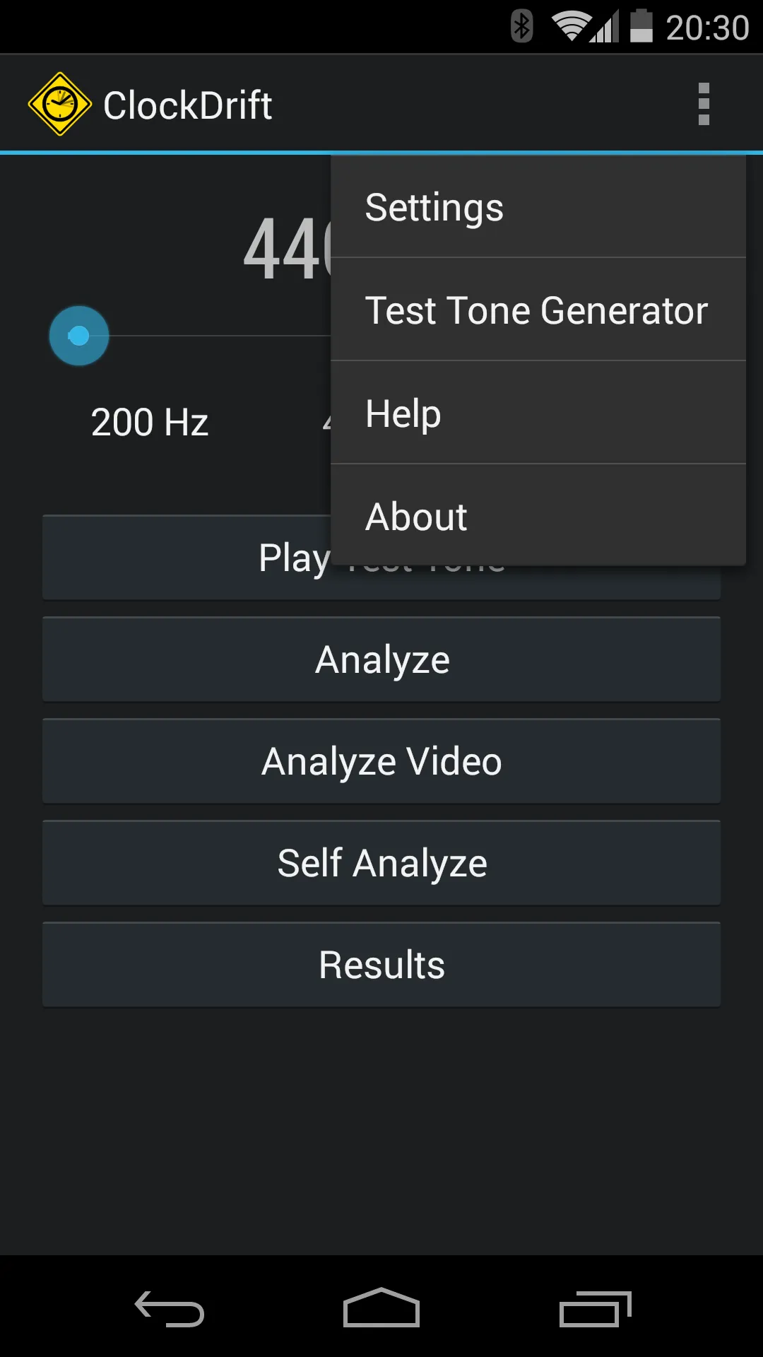
The action bar menu on the top right (3 vertical squares) provides access to the settings screen, this online help, and the about screen with build information and licenses of the Open Source libraries that the app is using. The Test Tone Generator opens a dialog to generate an uncompressed mono PCM wave file that gets saved to the root directory of the device’s memory named testtone-%samplerate%-%frequency%.wav. It can be copied to arbitrary playback devices for measuring their drift.
Analysis Screen
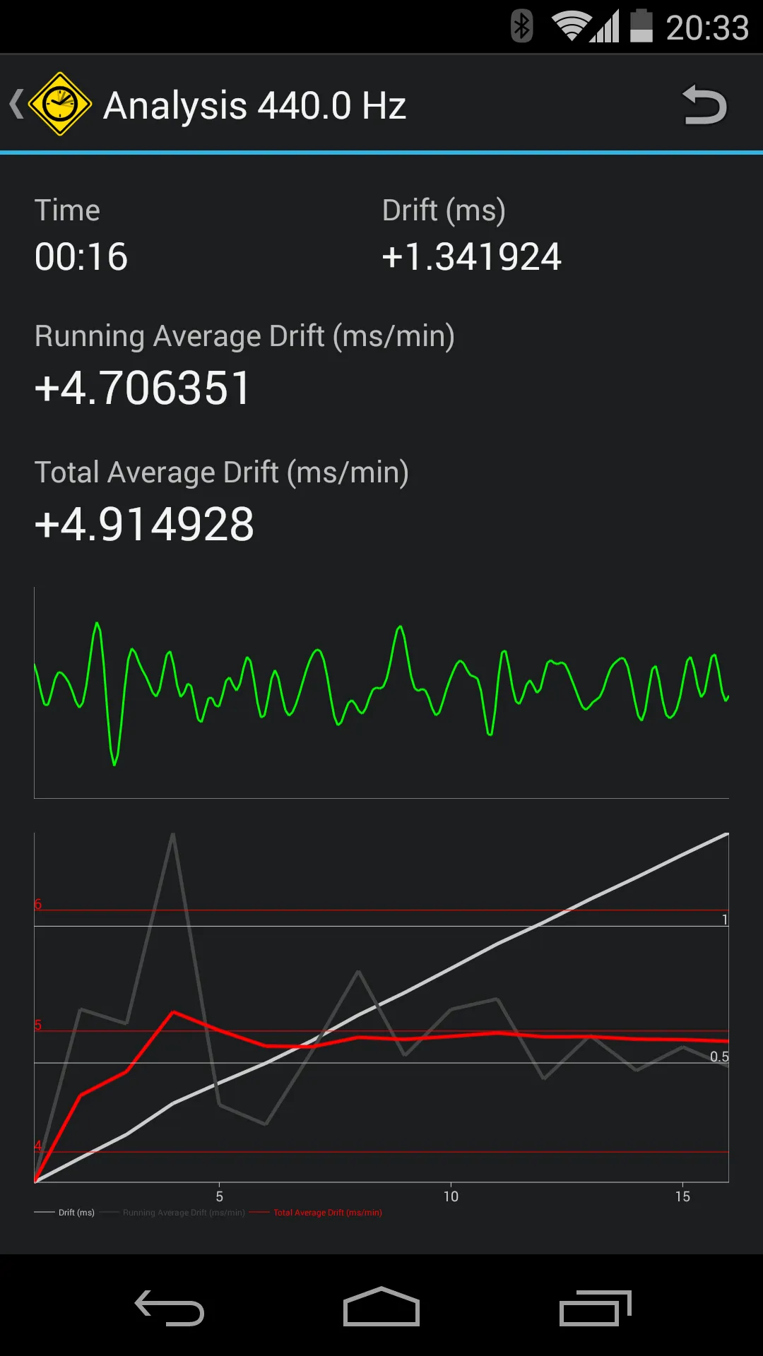
The analysis screen is the core of the app and displays results on-the-fly as the incoming signal is analyzed. It is divided into 3 areas. The button on the action bar resets all values and restarts the measurement.
- The top area displays the length of the measurement, the total drift detected throughout the measurement, a 1-second running average drift, and the total average drift over the whole measurement time. The unit of the total drift can be switched by tapping the value between (1) milliseconds and (2) seconds. The unit of the average drift can also be switched by tapping between (1) milliseconds per minute, (2) parts per million (PPM), (3) milliseconds per hour, (4) seconds per hour, (5) frequency, and (6) percentage. All values are displayed as relative deviation from their ideal value except for the frequency which is displayed as absolute value. PPM is the standard unit that drift in oscillators is usually specified in.
- The mid area displays the series of measured zero crossing distances of the target analysis frequency and can be used as an indicator of the incoming signal quality. The more stable the graph is, the better the pickup quality, the more precise the measurement (or the faster a stable average is reached), and the lower the jitter in the hardware audio processing pipelines. Since this graph is always bound by the min and max values over the visible interval, variations like in the screenshot are perfectly fine and can hardly be avoided. When the signal is OK, the graph is shown in green. If the signal strength is too low, either because the volume of the incoming signal is too low, the background noise is too high, or the signal cannot be picked up due to technical limitations, the graph is shown in red with an overlaid “weak signal” warning.
- The bottom area shows a graph of the developing measurement values, consisting of the total observed drift in light gray, the running average drift in dark gray, and the total average drift in red. A measurement can be regarded as finished when the red graph has horizontally stabilized, meaning that all irregularities in the analyzed signal have been averaged out. The light gray graph is usually turning into a diagonal line, showing the growth of the total observed drift. When measuring over a long time, this graph can also be used to detect nonlinearities in the measured drift, e.g. if the drift changes over time due to temperature changes from device heat.
To stop or finish a measurement, just press the back button. A result screen will appear, showing a summary of the measurement.
Results
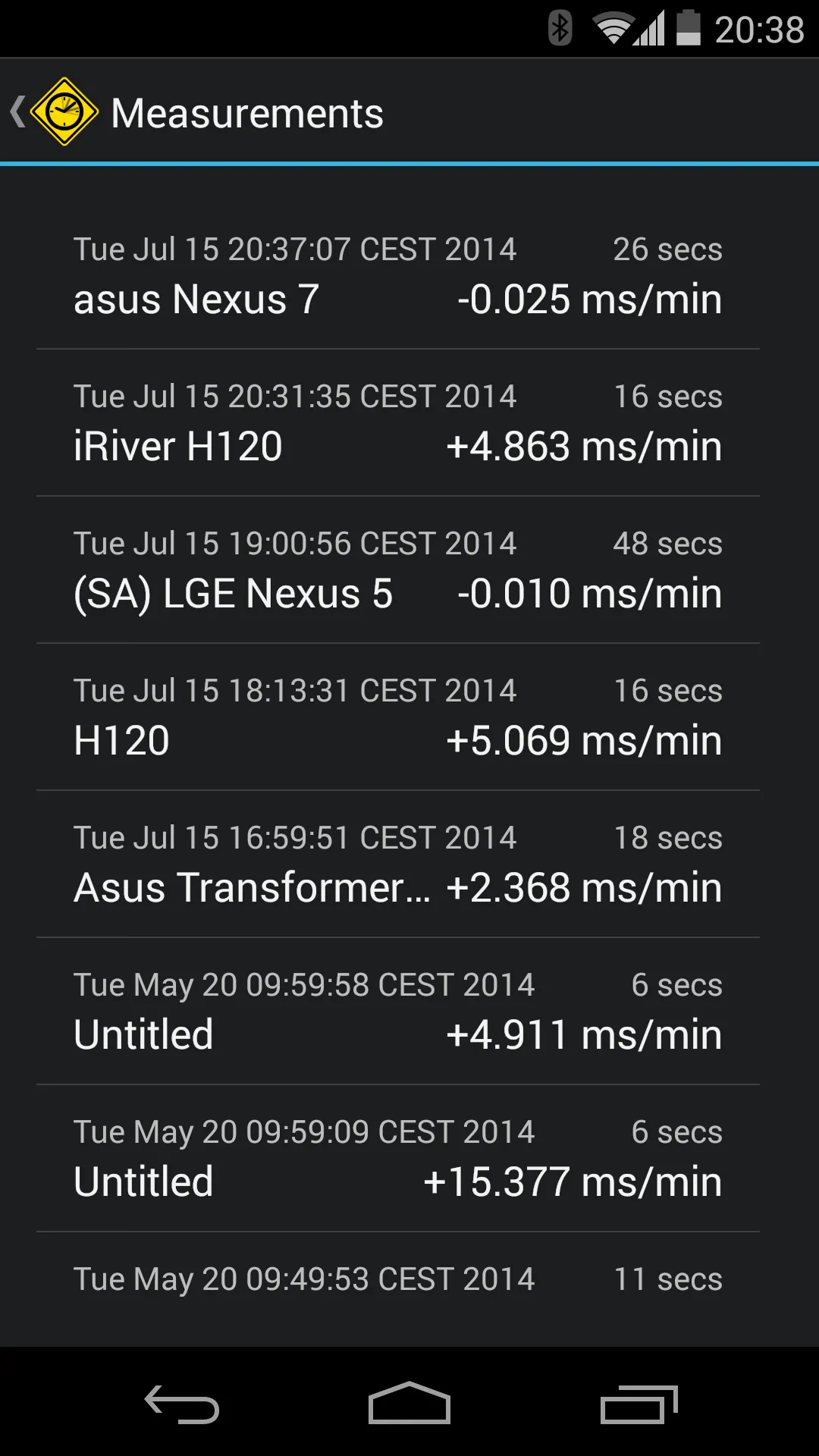
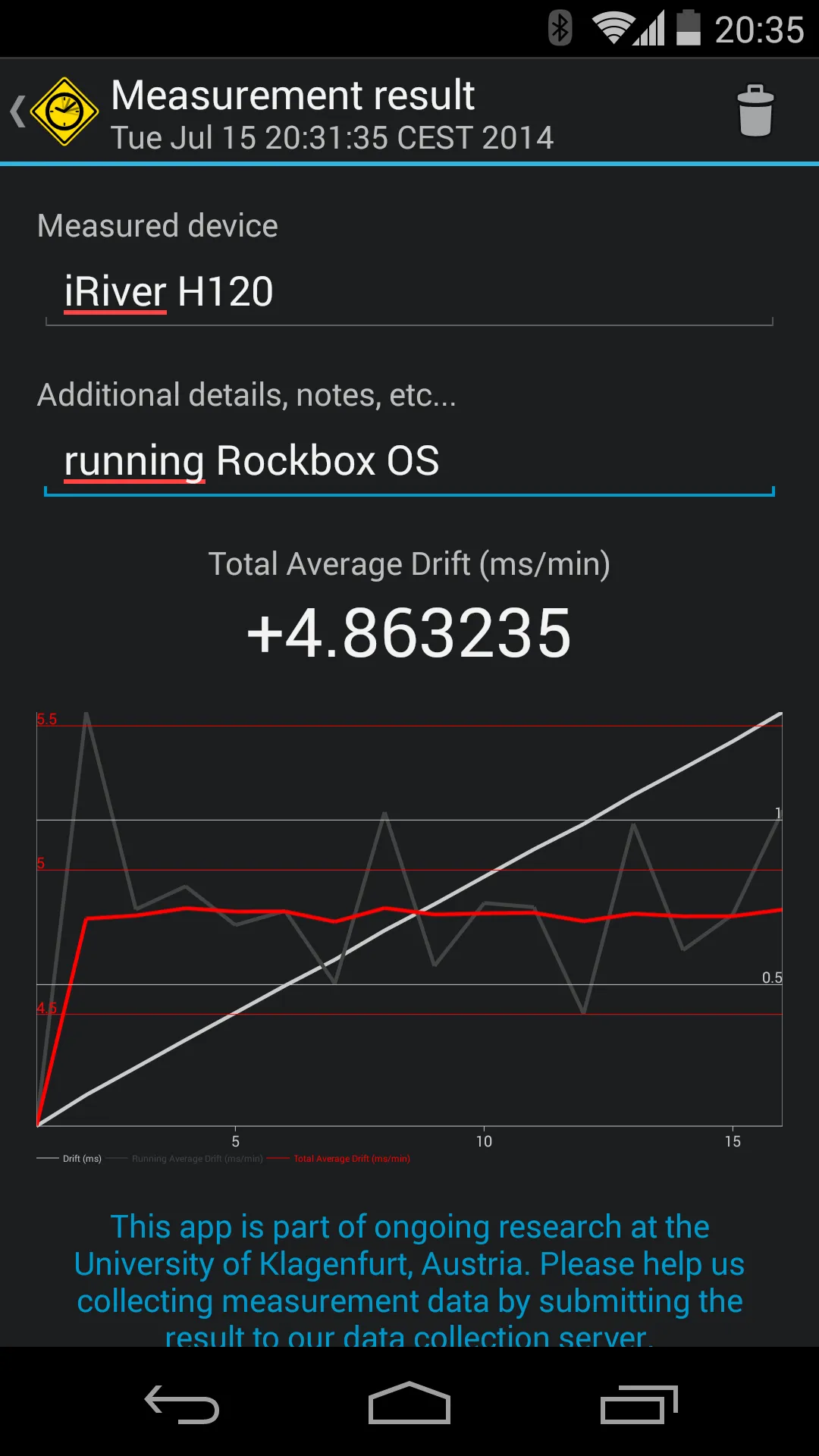
After finishing a measurement, the measurement result summary screen shows up. It gives the opportunity to dismiss the data by pressing the discard button on the action bar, or to save the data by just pressing the back button to return to the main screen. This screen offers meta two text fields to describe the measurement, namely the measured device (which is used in the results list and automatically filled when using Android Beam) and additional notes. The measured drift value can again be switched through the same units like in the analysis screen.
Saved measurements are collected in the results list that can be opened from the main screen. It gives an overview over all saved measurements ordered by descending date. The measurement summary screen can be accessed by a short press, which again offers the possibility to edit the meta text fields or delete the measurement. Results can also be batch-deleted by long-pressing an item, selecting multiple results, and pressing the delete button on the action bar.
Submitting a Result
The measurement result summary screen offers an option to submit the results to a University server. The aim is to collect many measurements to be able to detect absolute drift in often used devices automatically, and maybe even automatically calibrate ClockDrift for absolute measurements on selected devices. We also want to find out how much the drift varies between devices of the same type, make and model and if a database of device drifts can be generated automatically.
A measurement can only be submitted once. It includes the data of the three series in the graph and metadata (manufacturer, model) about the measured and submitted devices. Please take care to enter the correct name of the measured device before submitting, and also to not submit any confidential or private information that you may have written into the meta text fields.
Settings
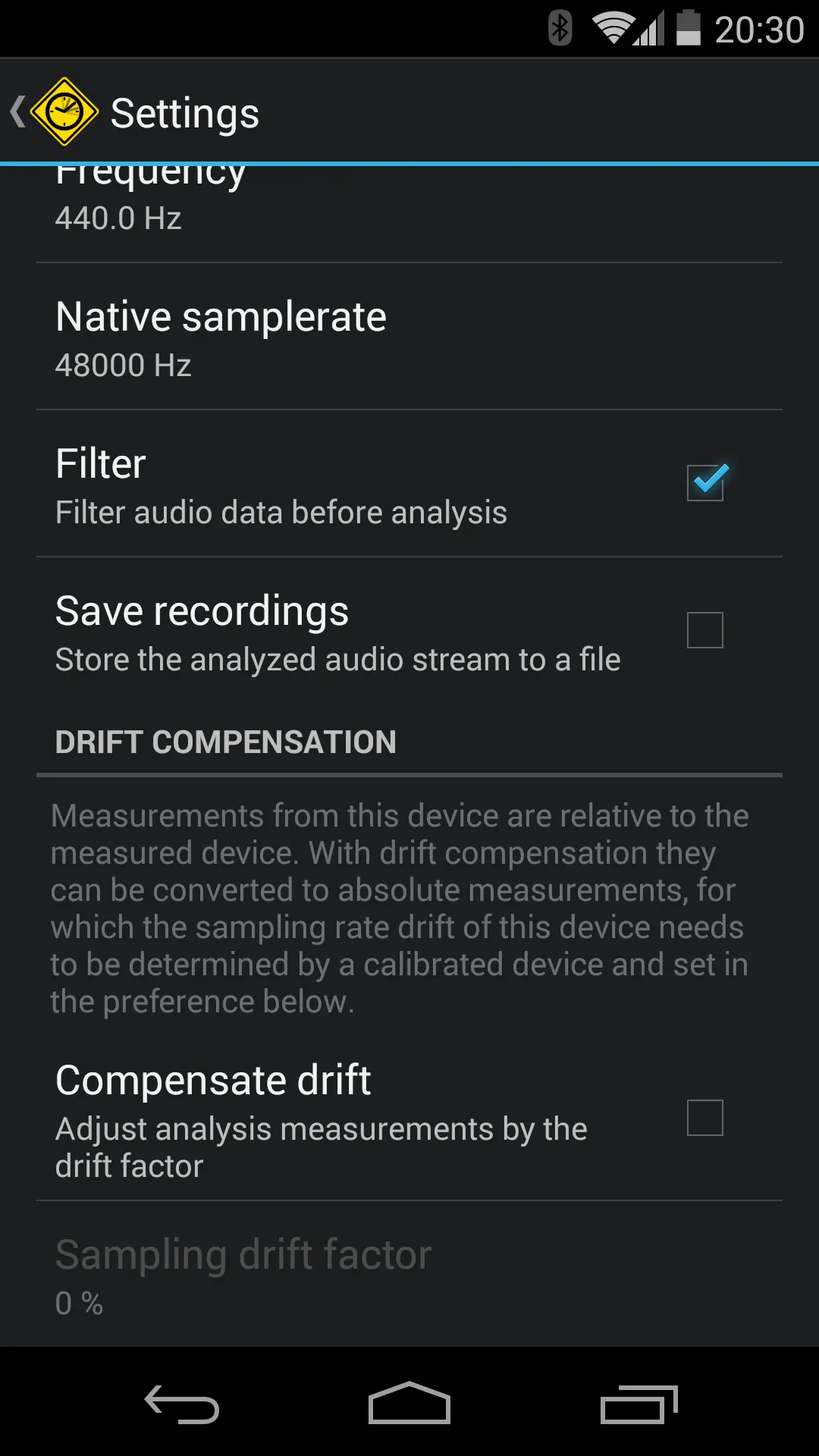
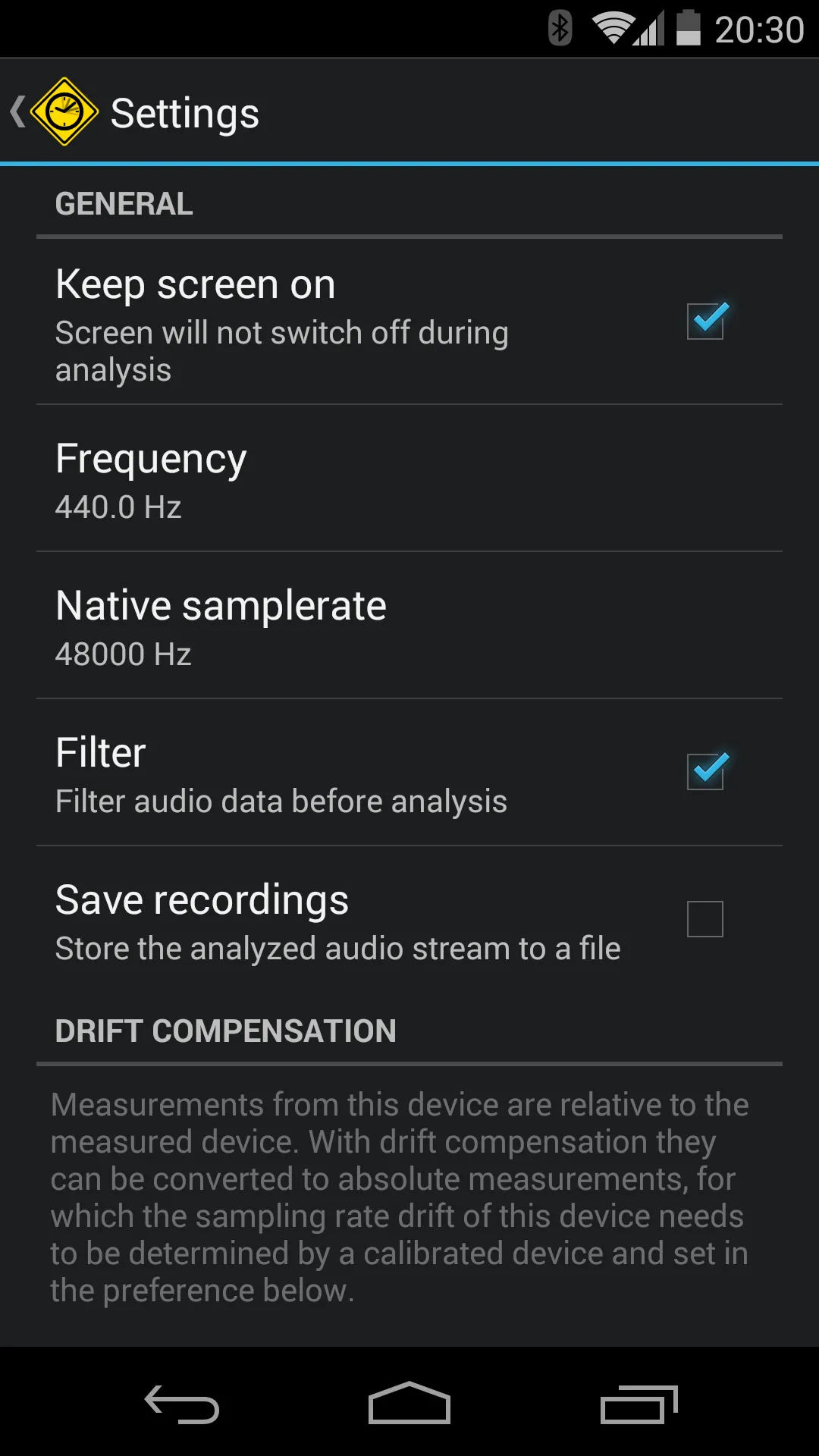
The settings screen contains mostly options that can be left at their default settings.
- Keep screen on prevents the screen from going to sleep during analysis. Since a measurement usually takes just a few seconds, this has only a negligible impact on battery life, but helps to obtain better results. By keeping the screen on, it not only helps to observe the measurement, but also to stop it at the right time without needing to physically interact with the measuring device. Physical interaction should be limited to stopping a measurement, as it introduces additional frequencies at the microphone and lowers the signal quality, leading to inferior results.
- Frequency can be used to set the measurement frequency. It is the same setting as in the main screen.
- Native samplerate is a read-only entry showing the native samplerate of the device, which ClockDrift always operates on (to avoid additional signal degradations through hardware-internal resampling). The measurement frequency must be in the frequency range that can be picked up by the device’s sample rate (f_max = sr/2, minus some roll-off pad).
- Filter decides if the incoming signals is filtered with a band-pass filter centered at the target analysis frequency. Switching it off saves processing resources but is only recommended in a quiet sound booth.
- Signal strength check monitors the energy of the incoming signal and pauses the measurement if it is too low,
- Save recordings decides if the analyzed signal is saved to a file in the storage memory. Can be used for further analysis of the file, e.g. on a computer workstation.
- Compensate drift is the most interesting setting. If the absolute drift of the device is known, this option can be activated and the drift factor entered as a deviation from the ideal value in percent. A drift factor of 0% means no drift, a drift of +0.05% means that the sampling clock of the devices runs too fast by 0.05%, which, e.g., translates to a real sampling rate of 48024 Hz compared to the nominally specified 48000 Hz. The drift factor will be incorporated into measurements and transform them into absolute readings.
Video Analysis
ClockDrift is designed to measure the drift in audio sampling clocks and operates on the audio hardware only. Precise measurements in the lab have shown that the drift slightly changes when recording video instead of pure audio, from which I assume that
- video recordings usually use the same clock signal as audio recordings, and
- the drift rate slightly changes because of increased heat from much higher processing demands of video, but
- the audio drift can be taken as an estimate for the video drift.
I have identified a single device in my lab, an Acer A200 tablet, that seems to use a separate clock for video recording, opposed to video playback, audio recording and audio playback, which all use the same clock. Its video recording drift was measured at -33.25 ms/min, the audio recording drift at just +0.80 ms/min.
Starting with Android 4.1, ClockDrift supports measurements in pre-recorded video files (Analyze Video option in the main screen). To determine if a device has different video and audio clocks, a measurement should be conducted twice. One time directly with the app, the second time by recording the test signal with a video recording app and then using the video analysis function. If the results are significantly different, you might have identified a device with different clocks.
Tips
- Frequent “weak signal” warnings? Turn up the volume of the test tone, put the devices more closely together, and make sure that their frequencies match. As a last resort, switch off the signal strength check in the settings menu.
