Casalux Ambiente AFL-1 WLED Upgrade
-
 Mario Guggenberger
 - November 3, 2025
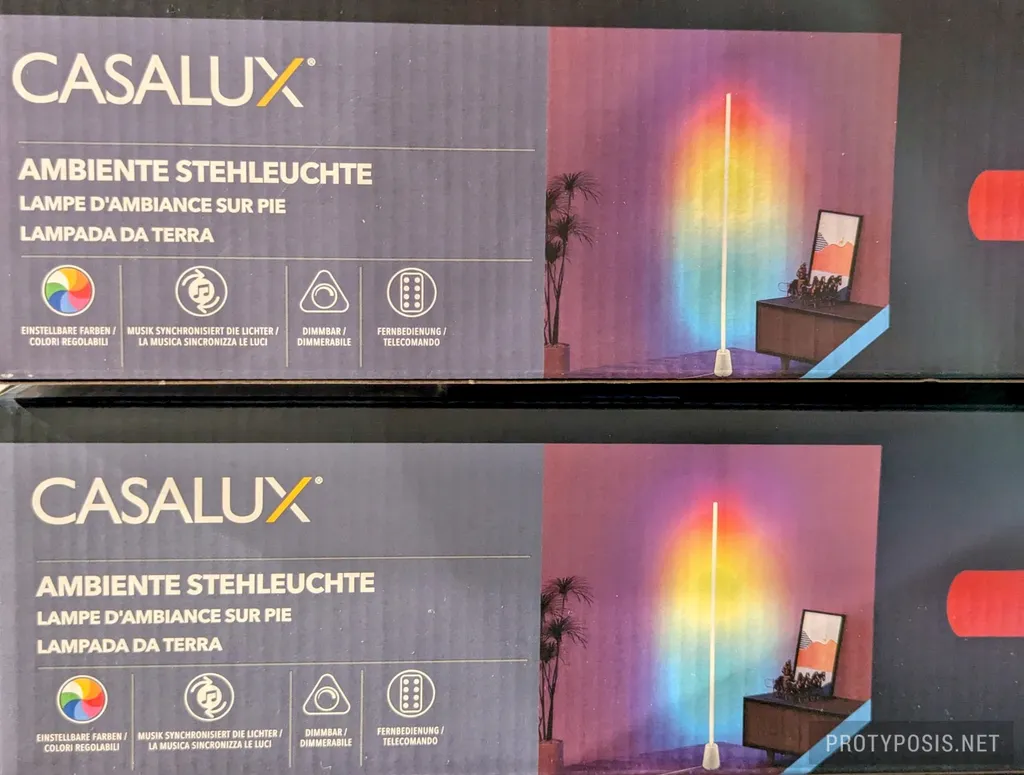
The Casalux Ambiente AFL-1 floor lamp, sold by Aldi/Hofer for ~€18, is a great base for smartification with a simple WLED upgrade. Here’s a teardown and upgrade guide.
The lamp includes a 1.3m cylindrical light bar, a stand, a 12V/1A power supply, and an IR remote. It’s available in black and white. Assembly is straightforward: insert the light bar into the stand, twist to lock, and connect the power supply. The IR remote then allows selection of solid colors, animations, and an audio-reactive music mode.
Disassembly and Analysis
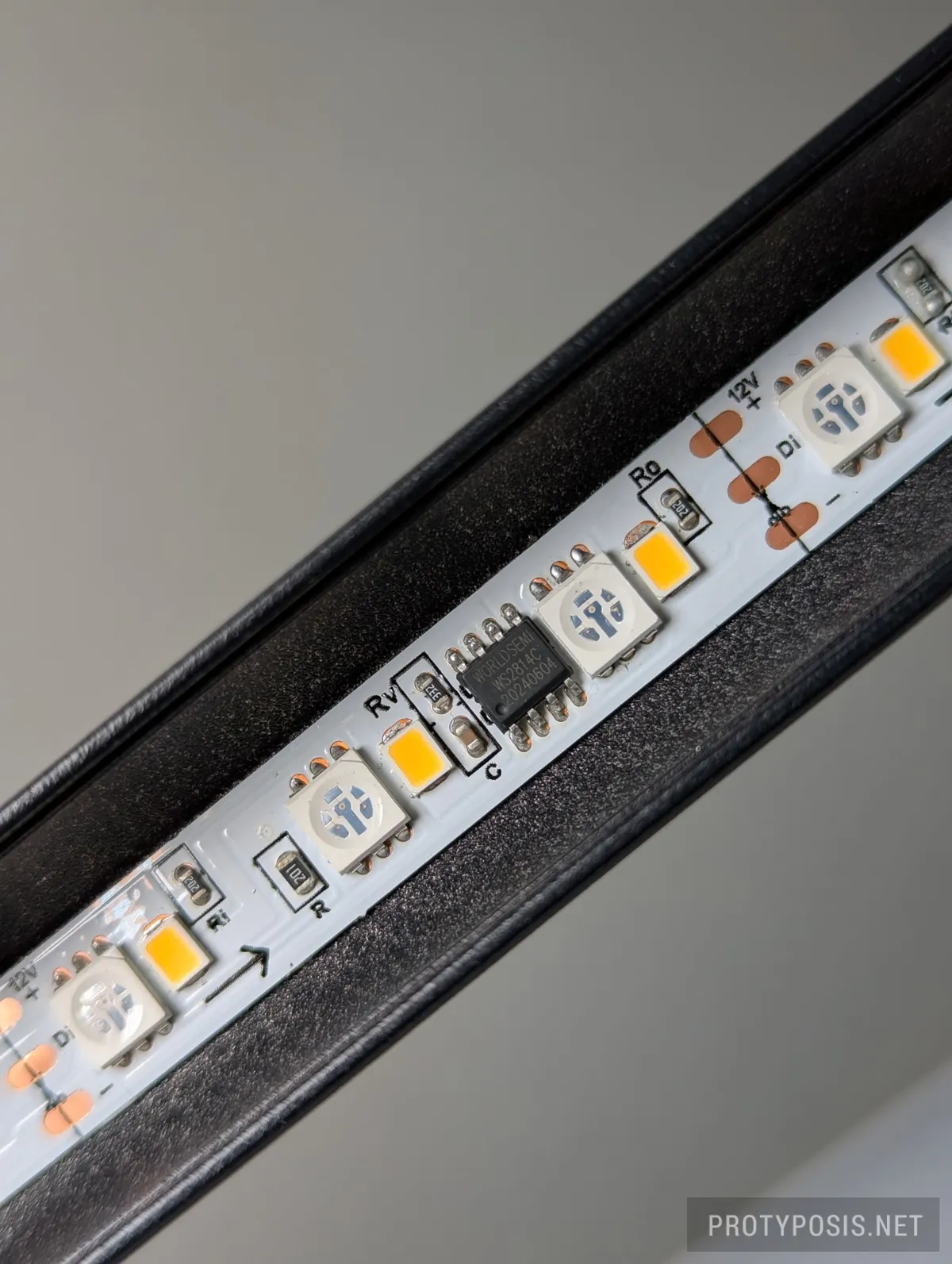
The light bar is a semi-cylindrical aluminum LED profile with a milky diffuser. It serves as both housing and heat sink for a glued-in 12V WS2814 strip. The strip has 25 addressable RGBW LED pixel triplets — a total of 75 RGB5050 and 75 warm-white SMD2835 LEDs (3000K). A polarity-correction IC on the bottom ensures proper operation because the light bar can be inserted facing either toward or away from the IR receiver and power input.
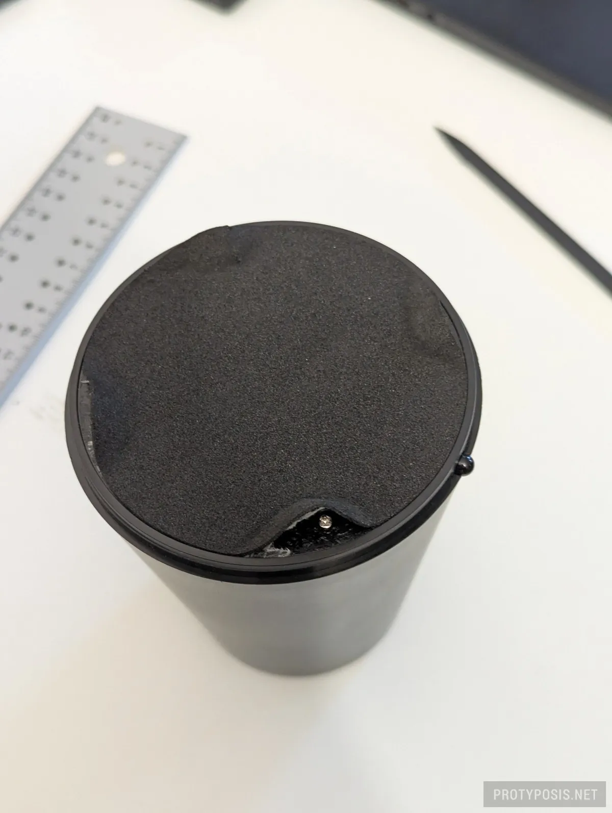
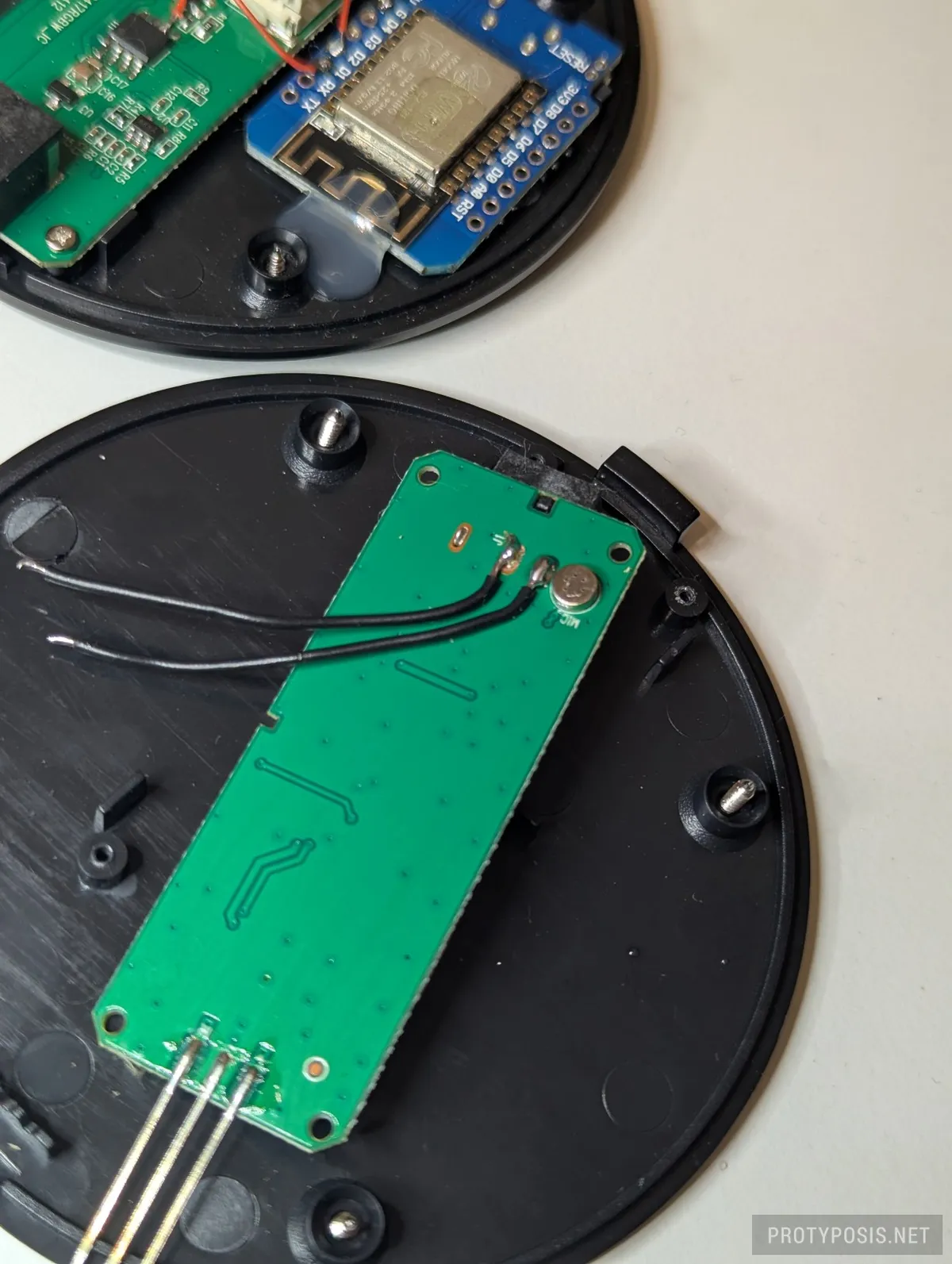
The stand can be opened by removing 4 screws. Inside is a weight for stability and the controller board. This board holds the 12V input jack, IR receiver diode, microcontroller, JST connector for a cable to the light bar, a microphone, and supporting circuitry.
The microcontroller has 8 pins:
- Pin 1 receives 5V power through an HT7550S LDO regulator from the 12V supply.
- Pin 5 outputs the LED data signal through a resistor to the LED strip.
- Pin 6 controls a 12V A1SHB 2.2 A MOSFET via a J3Y transistor, where a 5V (reduced by resistor to 4.1V) high signal turns it on and 0V low turns it off.
- Pin 8 is GND.
The remaining pins connect to the microphone and IR receiver and were not examined in detail.
-
Detailed look at LED strip -
Remove 4 screws to open case -
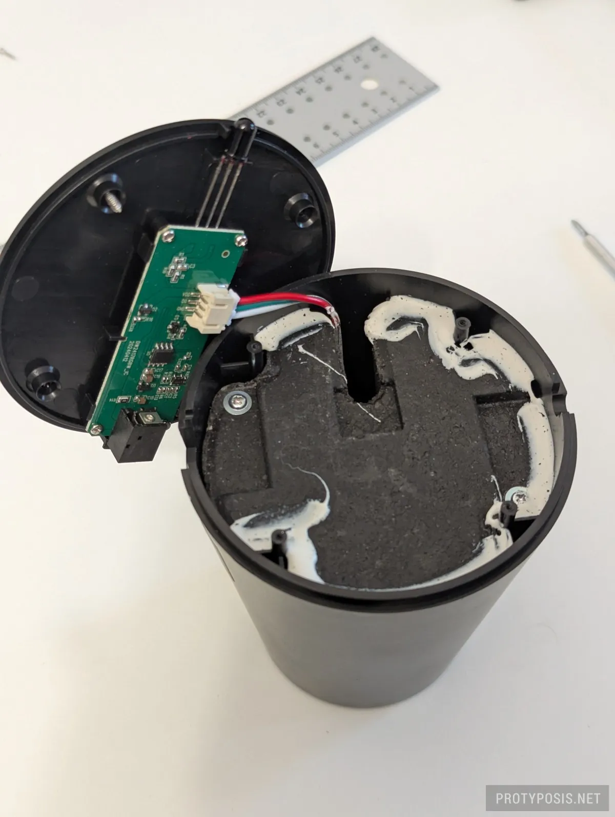
Opened case with controller board, cable to strip socket, and base weight -
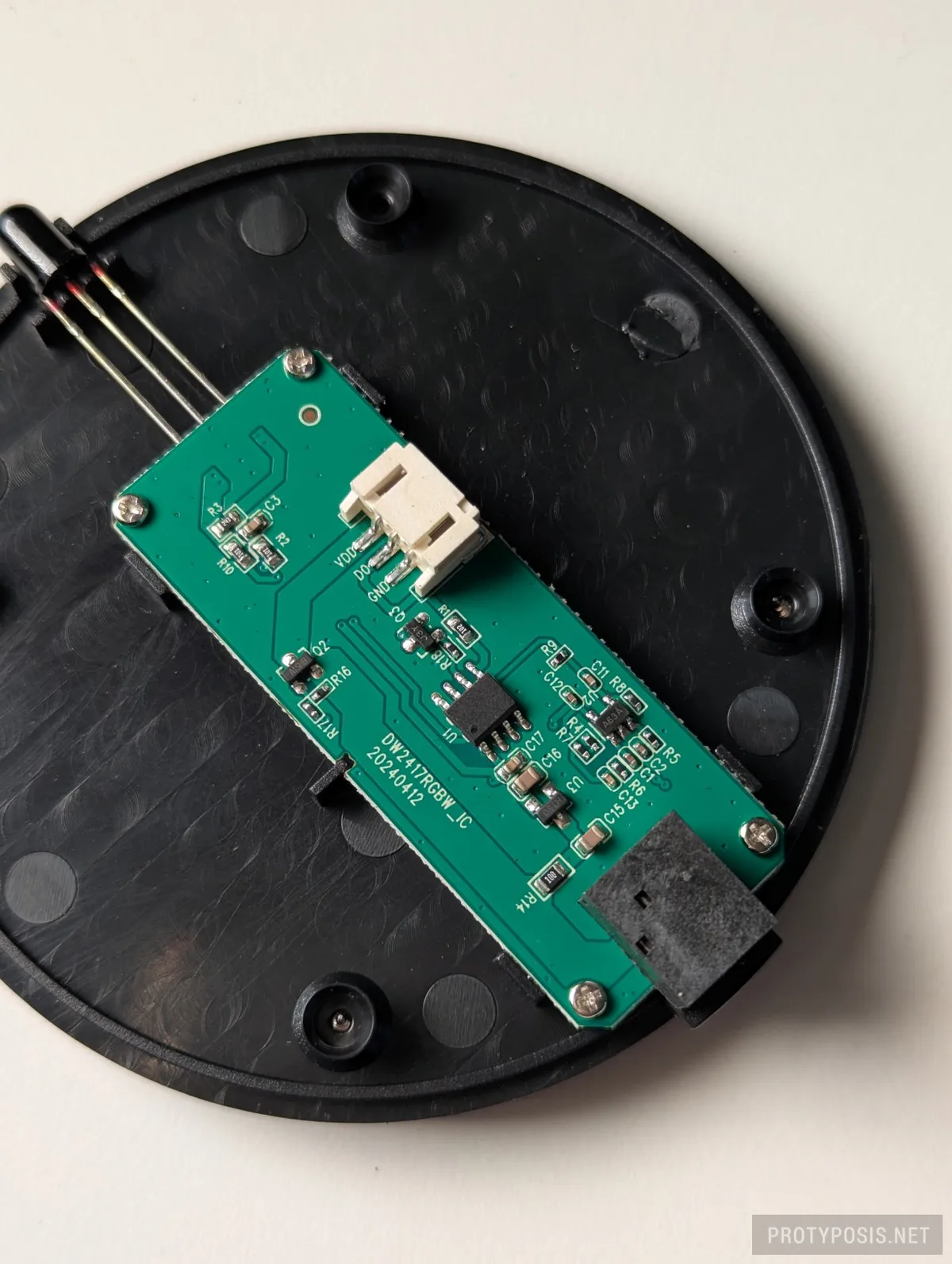
Detailed look at controller board front side -
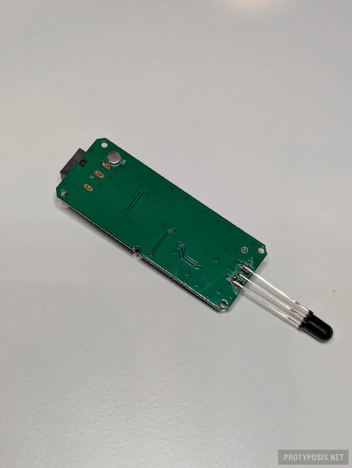
Detailed look at controller board back side
Upgrade
Since the existing microcontroller will be replaced by one running WLED, it must be disconnected from power by isolating Pin 1. I desoldered it so the lamp could be restored to stock later, but cutting the pin or trace would also work (or removing the microcontroller entirely).
My first attempt used an ESP32-C3 SuperMini connected directly to Pins 1, 5, 6, and 8. This compact design worked but had two major issues: the ESP32-C3-Zero became very hot (around 65°C in a ventilated room), and the LDO regulator became even hotter (82°C) and may be undersized for the ESP’s current draw. This combination seemed unsafe for the tight, unventilated space in the stand.
The final upgrade uses an ESP8266 D1 Mini, which runs cooler. It also replaces the LDO with a “Mini 560” 5V buck converter. Both fit beside the original controller board. The converter input connects to the 12V jack on the PCB’s back, and its 5V output powers the ESP8266. Two GPIOs are used: GPIO5 (D1) controls the MOSFET via Pin 6 of the old microcontroller, and GPIO4 (D2) drives the LED data line. For reliable operation, the data resistor must be bypassed and the wire kept as short as possible — the WS2814 strip is speficied for least 3.5V logic, and the ESP’s 3.3V signal only works reliably with minimal voltage drop.
-
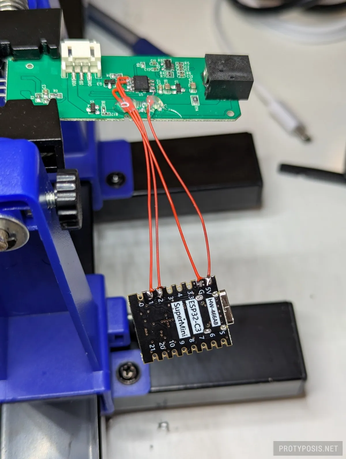
Prototype mod (not recommended) -
12V power source on back side -

Final wiring and assembly with buck converter and WLED controller
WLED Configuration
To make the LED strip work correctly in WLED, use these key settings:
- Enable automatic brightness limiter:
on - Maximum PSU Current:
850mA (included PSU supplies 1A and we leave some headroom for the ESP etc.) - LED output 1:
SK6812/WS2814 RGBW - mA/LED:
Custom - max. mA/LED:
80mA (see next section for explanation) - Color Order:
BRG - Swap:
W & G - Length:
25(the 75 physical LED pixels are addressed in triplets, so WLED controls just 25 pixels) - Data GPIO:
4(depends on your wiring) - Relay GPIO:
5(depends on your hardware setup) - Invert:
on
Brightness and Current Limiting
According to https://wled-calculator.github.io/, a 12V WS2814 strip with 75 RGBW LEDs draws about 1.78A when all four channels are fully lit (roughly 72mA per LED triplet). Because the included power supply only provides 1A and the ESP also consumes a considerable amount of current, brightness must be limited. The original lamp is specified at 5.7W (0.48A @ 12V) and seems to avoid higher currents by never lighting multiple color channels simultaneously at full power.
WLED doesn’t account for triplet-addressed strips like this one, so the current limit must be set manually. Setting the per-LED limit to 80mA accounts for the 75 physical LEDs and keeps the total draw within safe limits. For maximum safety, 90mA can be used (that’s WLED’s 12V 30mA preset multiplied by the triplet length).
For validation, typical white SMD2835 light strips are specified at 4.8W/m with 60 LEDs/m, or 7mA per LED (4.8W/60LEDs/12V = 7mA). Typical RGB5050 strips are rated 14.4W/m with 60 LEDs/m, or 20mA per LED (14.4W/60LEDs/12V = 20mA). That’s 27mA per RGBW pixel and 81mA per triplet. So 80–90mA per LED in WLED is a reasonable estimate. Higher equals safer, but also lower (max) brightness.
Future Improvements
Better Power Adapter
At full brightness, the LED strip draws up to 1.78A according to the WLED calculator, exceeding the supplied adapter’s 1A limit. A higher-rated 12V/2A power source would therefore be ideal and would allow disabling WLED’s brightness limiter. The MOSFET and PCB traces appear capable of handling this load, though it’s uncertain whether the JST connector and twist-lock wiring to the LEDs are rated for it. The long-term impact on LED lifespan is also unknown.
Microphone
It may be possible to connect the existing microphone to the ESP and use WLED’s sound-reactive features. In my case, I skipped this because I control all WLED lamps from a device that already captures audio directly from HDMI.
Enable IR Remote Control
It may be possible to reuse the existing IR diode on the board for WLED’s IR remote control, by wiring it to an appropriate GPIO on the ESP. The included remote could then be used to control WLED.