RGB LED Party Spotlight WLED Upgrade
-
 Mario Guggenberger
 - May 10, 2023

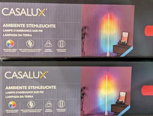
What’s better than an RGB party spotlight? An RGB party spotlight with the great LED controller firmware WLED! This is a guide how to easily upgrade the USB PartyPar 6 RGB light by Fun Generation.
The light is available in different variants (with/without IR remote) and also from different brands, e.g., Eurolite LED PK-3 USB TCL Spot. It originally has 3 lighting modes: a fade mode where the color gradually changes, an “auto” mode where it toggles between fading and instant color changes, and a sound-reactive mode via a built-in microphone. Power is provided via Micro-USB, a power adapter is included (rated 1A).
I originally bought this light just for its chassis, because I needed something with spot lenses to put addressable LEDs and a WLED controller into. I therefore picked the cheapest light I could find that fulfills that requirement (14€ in April 2023). It turned out though that the built-in LEDs are quite powerful (6x 3W) and the controller board can be reused as LED driver. The LEDs can’t be controlled individually this way, but it’s a much simpler modification and the quality of the lenses is bad anyway, so the additional effort probably wouldn’t pay off :) The internal controller board uses a holychip HC89F0421 (datasheet) microcontroller in a SOP16 configuration, with 3 PWM outputs controlling the light color, and in this example it’s going to be replaced by an ESP32 in D1 Mini format which takes over the PWM output.
Build Instructions
- Open the chassis.
- Remove the controller board.
- Desolder (or cut) pin 1 (
VDD) of the microcontroller to disable it. - Solder a pin header into the 6 holes on the top left of the board. (This is a JTAG port for the on-board microcontroller, but we can re-use it now that it’s deactivated. The leftmost pin is
GND, the rightmost 5VVCC, and we’ll use them to power the ESP.) - Solder wires between the 3 microcontroller pins (pins
2,3,4) left ofVDDand the pin header. (This is where we’ll inject the RGB PWM signals from the ESP.) - Prepare the ESP by installing WLED and soldering pin headers. I used GPIOs
16,17, and21for R, G, and B (I selected them because they don’t lead to undesired color effects at WLED boot). - Connect both pin headers with 5 jumper cables. See picture 3 for correct assignments.
- Secure the ESP with hot glue inside the chassis.
- Close the chassis. You’ll have to bend the pin headers to flatten the installation and make it fit with the LED board.
-
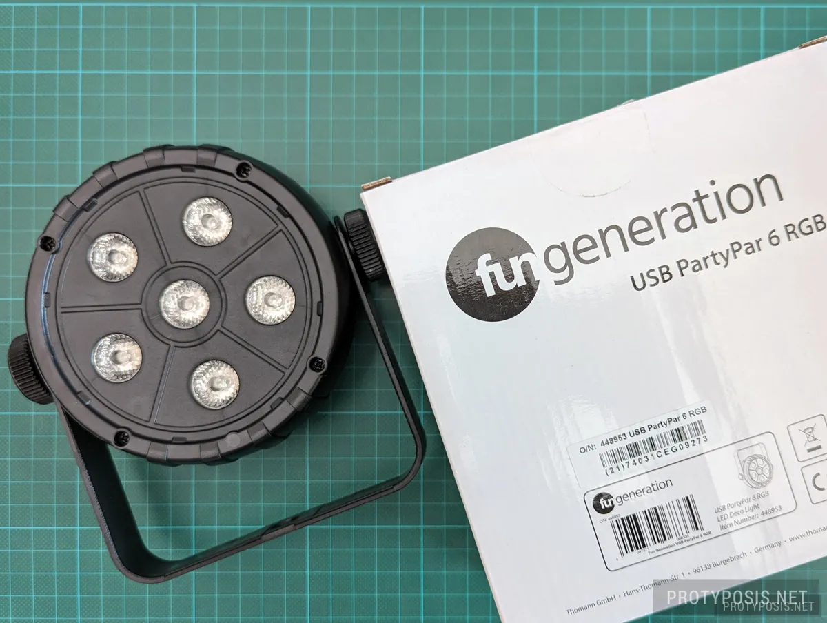
The unboxed light -
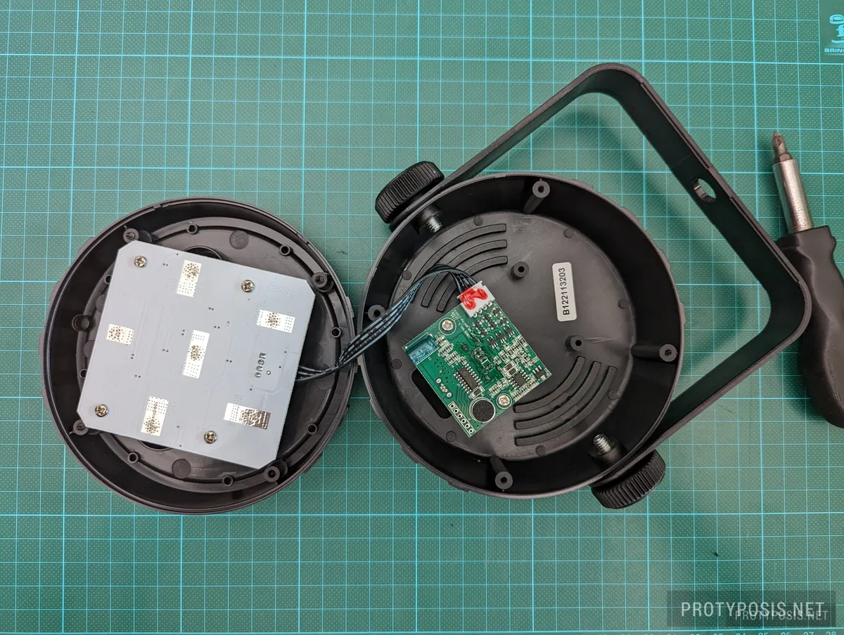
Open chassis with LED and controller boards -
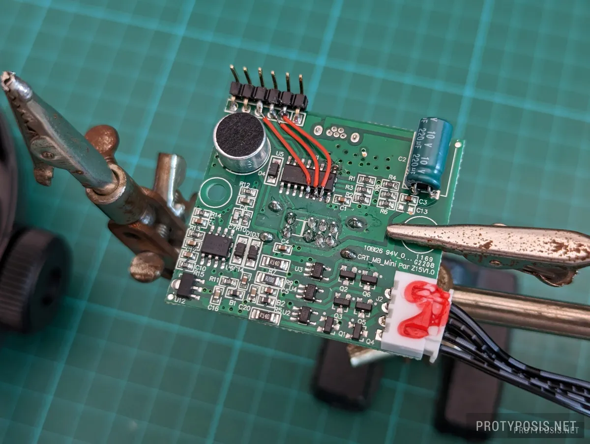
Modified controller board with bridged PWM channels -
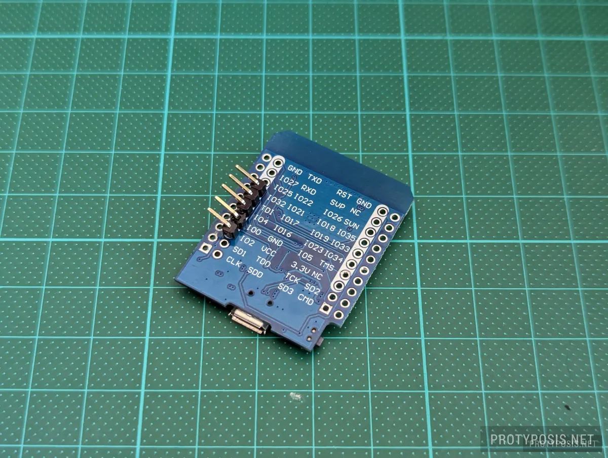
Pins used on the ESP32 -
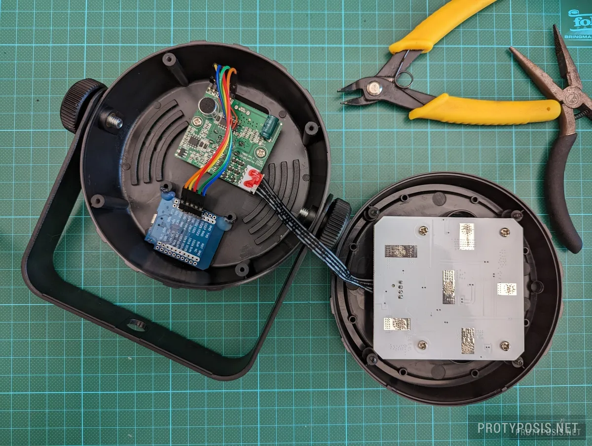
Finished upgrade
Upgrading to WLED makes it much more versatile and easily integrates it into smart homes, e.g., to display visual notifications. Even audio reactiveness is possible with one of the Audio Reactive or MoonModules forks or the upcoming WLED 0.14, but I did not attempt to re-use the built-in microphone because I use it as a UDP Sound Sync receiver.
Have fun with your new party light!